
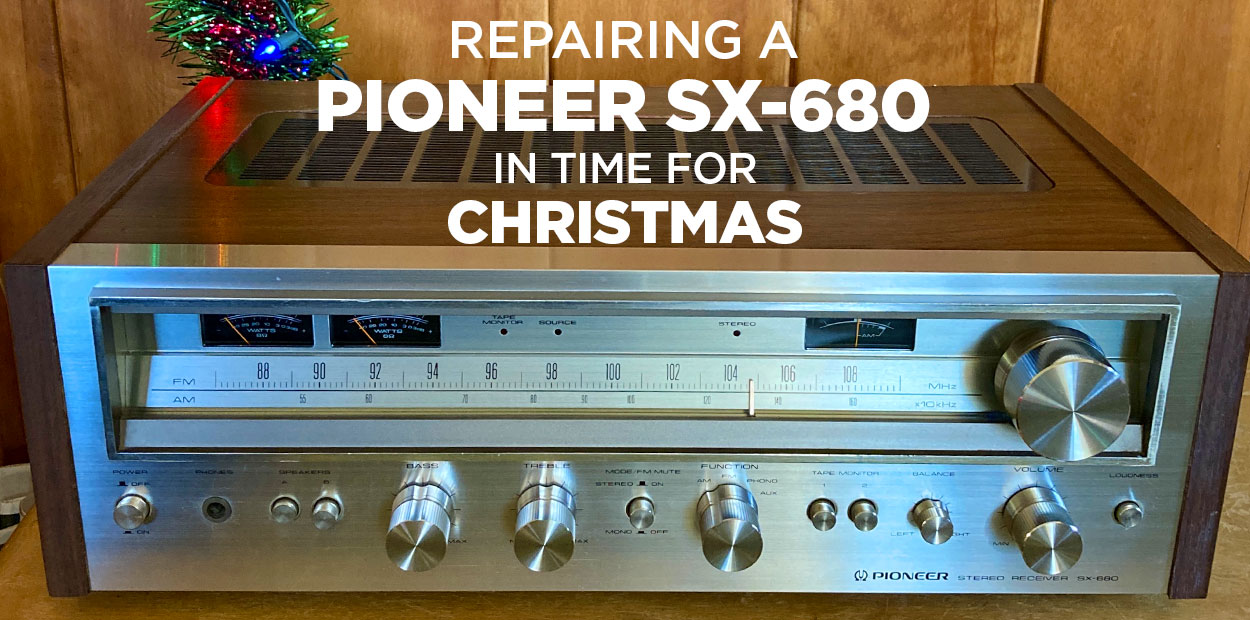
On the Bench: A Pioneer SX-680
Today we’ll cover a Pioneer SX-680 repair – including troubleshooting. Please note that there are high voltages present in this unit and if you are following along to repair your own unit, you are doing so at your own risk.
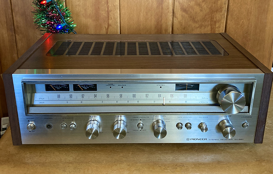
The Pioneer SX-680 is a stereo receiver that started production in 1978. It outputs a modest 30 Watts per channel into 8Ω at 0.1% THD with a frequency response of 5Hz to 100kHz. It’s no SX-1980 but still has a great look and excellent sound quality that gets plenty loud.
I have been on the lookout for a receiver upgrade for my brother-in-law, who was using a godawful Fisher “BPC” unit from the late 80s that was on its last leg.
A few weeks ago, a non-working Pioneer SX-680 showed up on Facebook Marketplace for $40. I realize the unit could have been completely trashed, but took the chance that it could be repaired, as it would make the perfect Christmas gift for my brother-in-law. I bought it.
Once home, I hooked up some speakers and fired it up. The lights turned on, but there was no audio whatsoever on any input. The unit was DOA. 😭
Pre-Repair Flight Check
Before beginning any repair, I generally follow these steps:
- Find and download the service manual and schematic (in this case, from the excellent HiFiEngine)
- Search through relevant Audiokarma threads to get a sense of common issues and component substitutions.
- Perform a visual inspection.
My search through Audiokarma yielded this excellent thread by user Johnny_Law that documented his successful repair of a unit with the same issue, and another great thread that gave a list of replacement components and substitutions. I utilized both of these threads to successfully complete my repair and restoration.
Opening Up the Pioneer SX-680
Our Pioneer SX-680 repair starts with opening the unit up and doing a visual inspection.
The main things I look for are: burnt or obviously damaged components, exploded or bulging capacitors, heavy dust build-up, and discolored/burnt sections of PCB. I also try to gauge if the unit has been repaired before or not.
To get the best view, I removed the rather massive heat sink from the center of the unit, along with the two STK-0039 power packs that were attached to it. To do this just takes removing a few screws from both sides of the heat sink, along with two PCB boards that are attached to it.
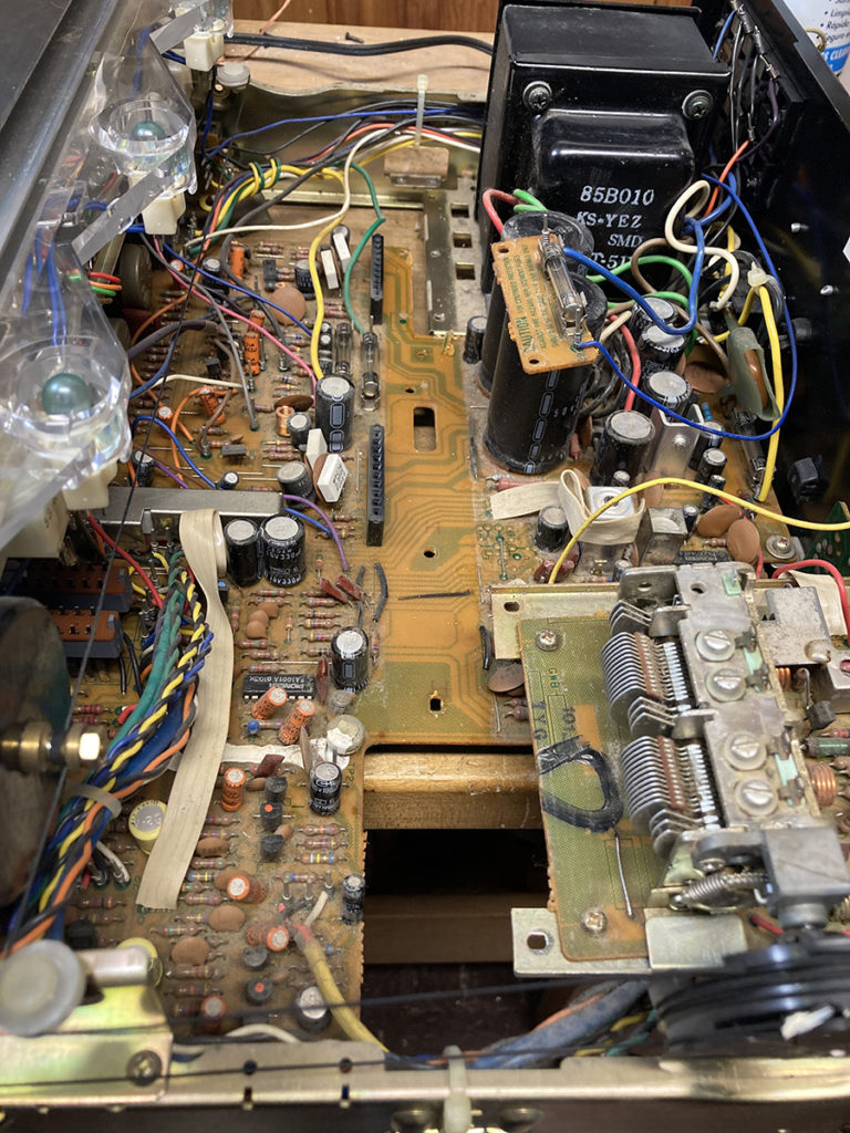
In this unit, things looked pretty good. Nothing stood out as abnormal.
Voltage Checks
I normally start troubleshooting at the power supply – to test if correct voltages are being supplied to different stages of the circuit.
Based on this Audiokarma thread, I started by testing voltages coming into the PCB at pins 11 and 12 – and followed them back through test points noted in the schematic. Be careful in this area – as C403 and C404 retain their high voltage even when the unit is unplugged.
When I got to R401, one side of the resistor measured 54.1 Vdc and the other side (feeding Q402) measured -0.6 Vdc! Something was amiss.
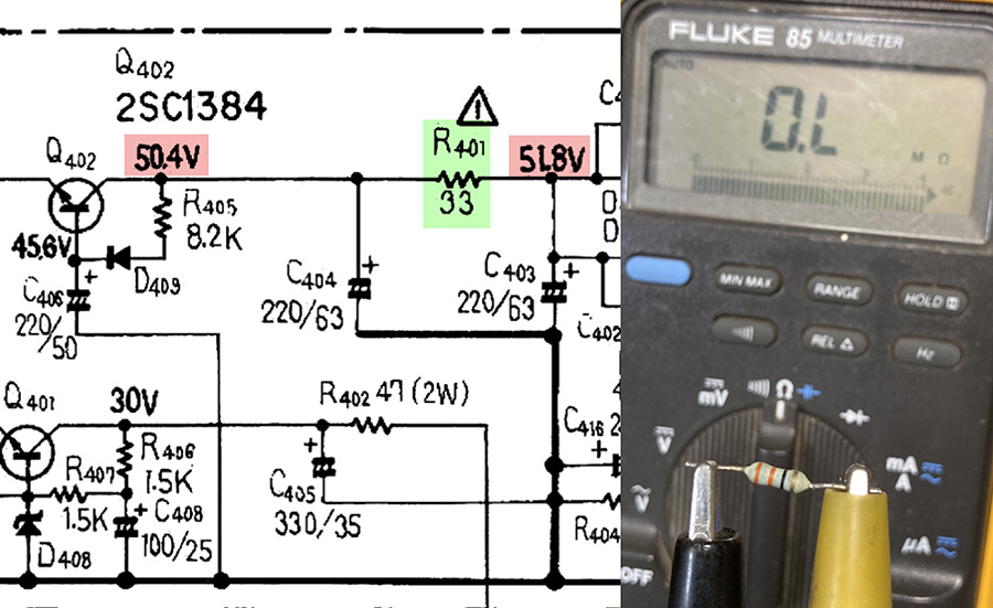
Indeed, removing R401 and measuring it uncovered the problem: it was open. The supplied voltage was not getting through. I replaced it with a 1/2 W metal film resistor.
Once I had replaced R401 and reassembled the receiver, the unit sprung to life and I was able to successfully run a cassette deck through the AUX channel to hear SOUND!
Testing the STK-0039 Power Pack
The SX-680 design utilizes STK-0039 power packs that use a Darlington type circuit to output 35W in one “IC-like” package.
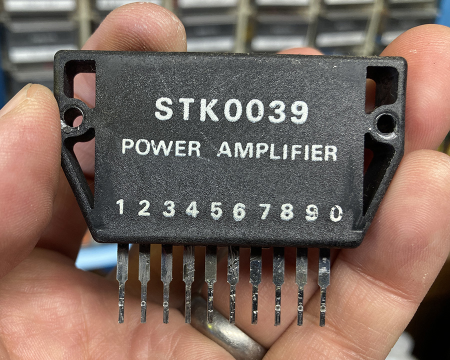
These STK-0039 packs can often fail – and if they do, authentic replacements are not readily available (or cheap). Most restorers dealing with a failed STK-0039 end up building their own out of discrete components, as documented on this Audiokarma thread that documents a successful build for an STK0050, which can be used in place of an STK0039.
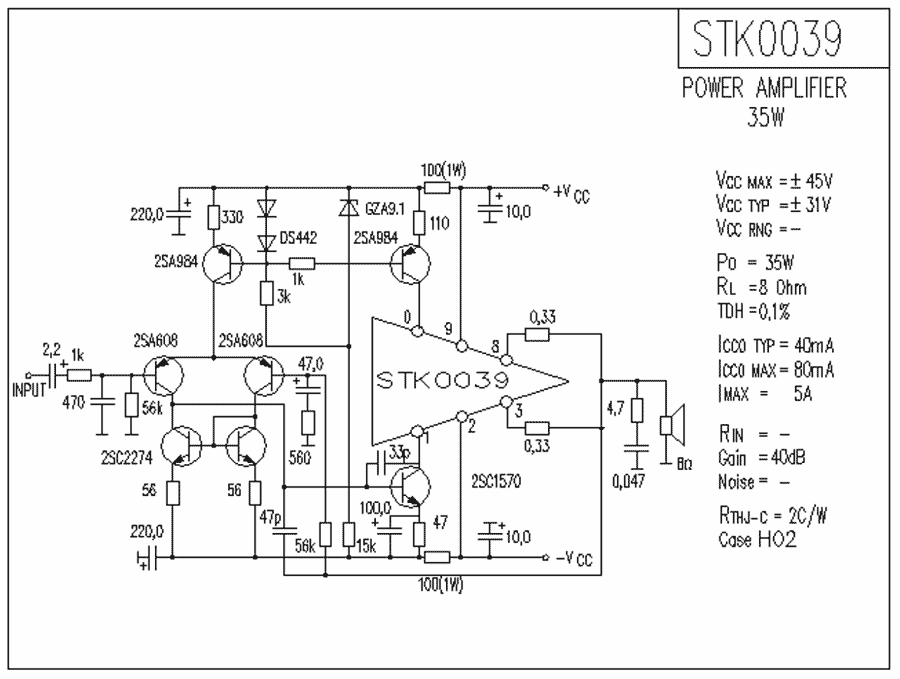
A quick voltage test of the STK-0039 can tell you if these are working as they should. Set your multimeter to DC voltage, connect the ground to the bare metal chassis of the SX-680, and carefully touch the different pins of the STK0039 to note their voltage readings:
| Pin | Specified Voltage |
| 1 | -1.4 Vdc |
| 2 | -34.5 Vdc |
| 3 | 0 Vdc |
| 8 | 0 Vdc |
| 9 | +34.5 Vdc |
| 10 | +1.4 Vdc |
In my case, the voltages checked out just fine and I was very happy to discover that my STK power packs were functioning normally.
Next Steps
Now that the problem has been successfully diagnosed and fixed, I can now take steps to electrically restore the unit to its original state while upgrading a few components along the way.
Click onward to read part 2 of this Pioneer SX-680 repair, in which I rebuild the unit by replacing electrolytic capacitors, failure-prone parts, and noisy transistors in the phono preamp.
Pioneer sx 680 I replaced the stk 0039 for the left channel and waiting for awhile I powered on the am fm radio works but when I switched it to phono left meter was going crazy left speaker sounded like it was looking for a radio station.
Hmm. Not sure what the issue is here. When in doubt, I always retrace my steps and check my work. If that all seems good – all I can say is that with these vintage units, sometimes when you repair one thing you just uncover more problems to fix! Good luck with your unit.
Thanks for sharing your project. I recently acquired a SX-680 that has a distorted channel, so your details will greatly help me (a novice) track done and hopefully correct the issues.
Glad to help – Hope your restoration was successful!