
A Pioneer SX-680 Rebuild
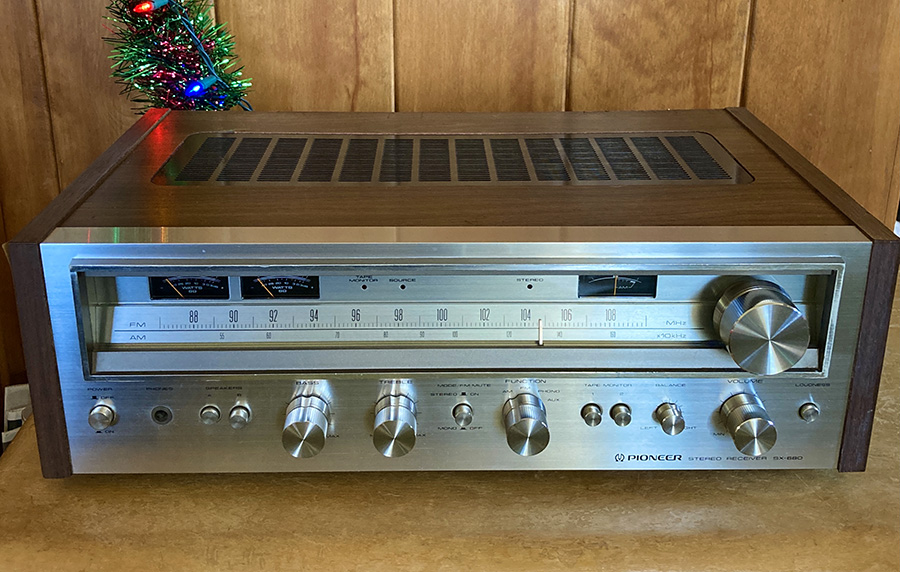
In Part 1 of this series, we repaired a dead Pioneer SX-680 that had no audio output. In Part 2, we’ll embark on a complete Pioneer SX-680 rebuild.
The rebuild will consist of:
- Replacing all electrolytic capacitors with high-performance modern equivalents.
- Replacing failure-prone or problematic components (namely, a few transistors and resistors) with high-performance modern equivalents.
Should you Replace Electrolytic Capacitors if they are Still Good?
There is some disagreement among repair techs over the practice of “re-capping” audio equipment. For myself, it takes so much time and effort to learn about and disassemble a piece of equipment that I’d rather just replace components like electrolytic capacitors that have a finite working life. In this case, since it is a Christmas gift to a relative, I’d rather do everything possible to ensure it has a long working life and minimize the chance it will stop working due to a failed component that I could have easily replaced.
Opinions aside – let’s take a look at the condition of the capacitors in this SX-680.
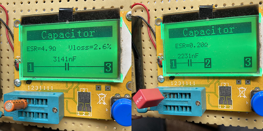
Here’s an example of why these capacitors should be replaced – and how you can improve performance even more with higher-quality components. On the left we see a 2.2 µF electrolytic capacitor that was pulled out of the phono preamp circuit. It’s capacitance value has drifted by 42% and it shows some substantial leakage (Vloss).
Leakage does not refer to electrolyte leaking out of the capacitor (although this can happen too!) – It refers to electrical leakage. The capacitor can leak DC voltage into the circuit – potentially throwing off the bias of transistors and thereby affecting overall performance. Replacing it with a brand new WIMA film capacitor brings it back to spec with much lower ESR and no leakage at all.
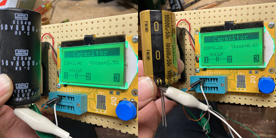
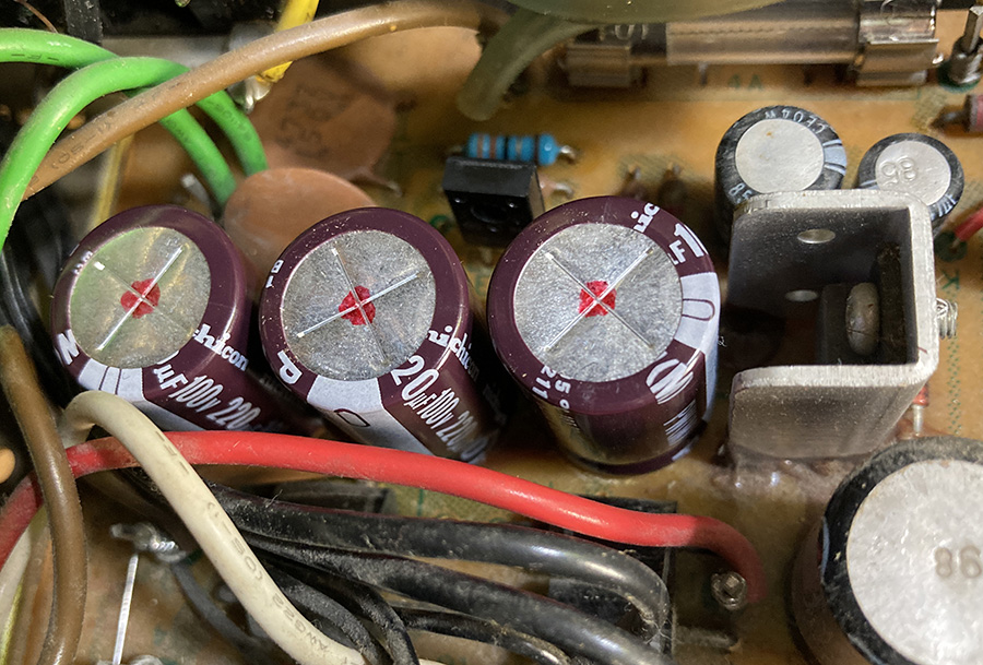
Here we see one of the two large power supply capacitors from the SX-680. Note that its capacitance value has dropped significantly from 8000 µF to 4941 µF – a downward drift of 38%. Less capacitance here will affect amplifer performance. Replacing it with a 10000 µF Nichicon with slightly lower ESR and low leakage will improve performance and long-term reliability. The slightly higher capacitance value of 10,000 µF will also improve performance.
Ready? Let’s Replace Some Caps!
The first thing I like to do is to make a list of the components I plan on replacing – all electrolytic capacitors, along with failure-prone components recommended to replace/upgrade based on advice from Audiokarma posts such as this one.
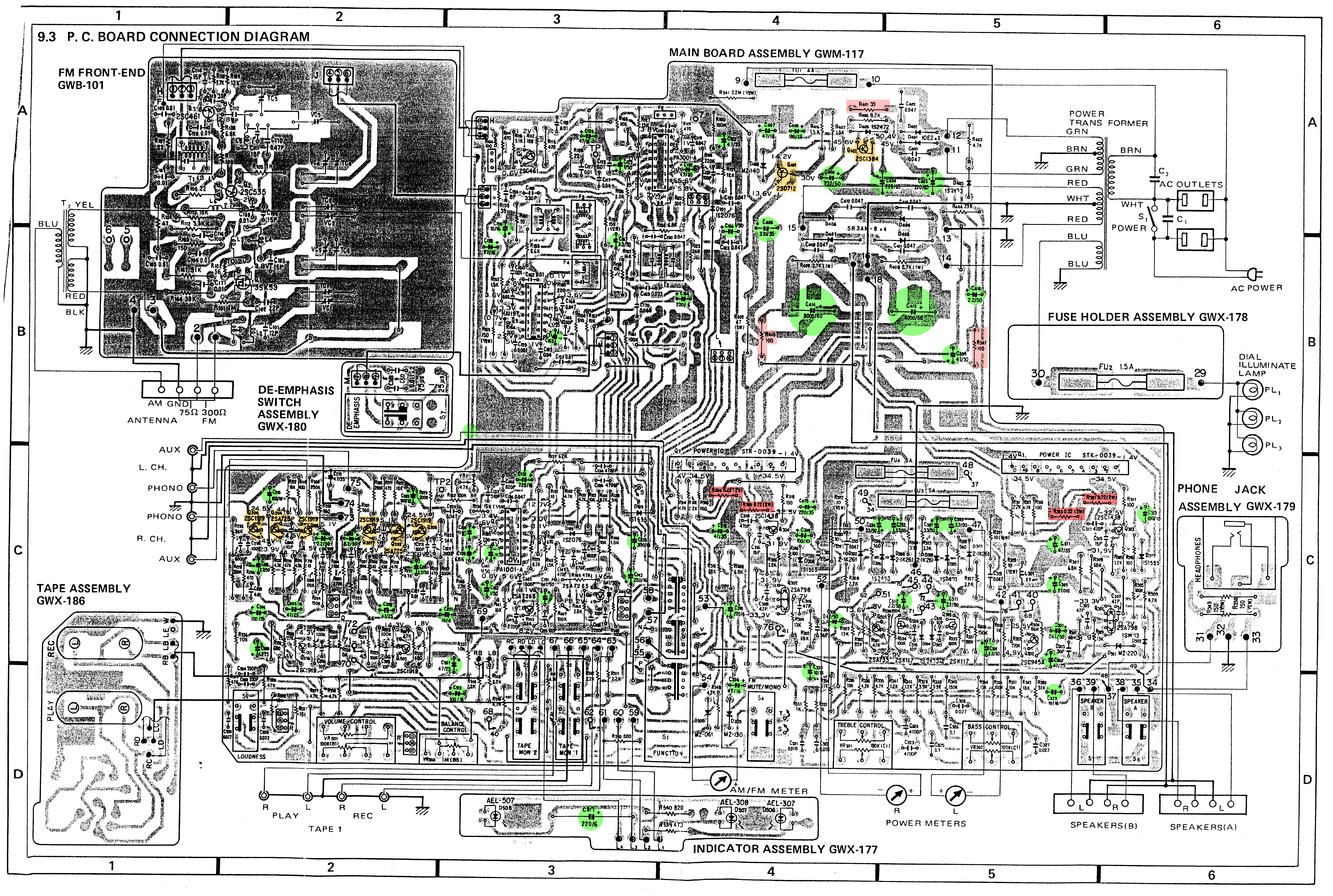
While I wait for the components to arrive, I make a visual guide to where these components are located on the PCBs I’ll be working on.
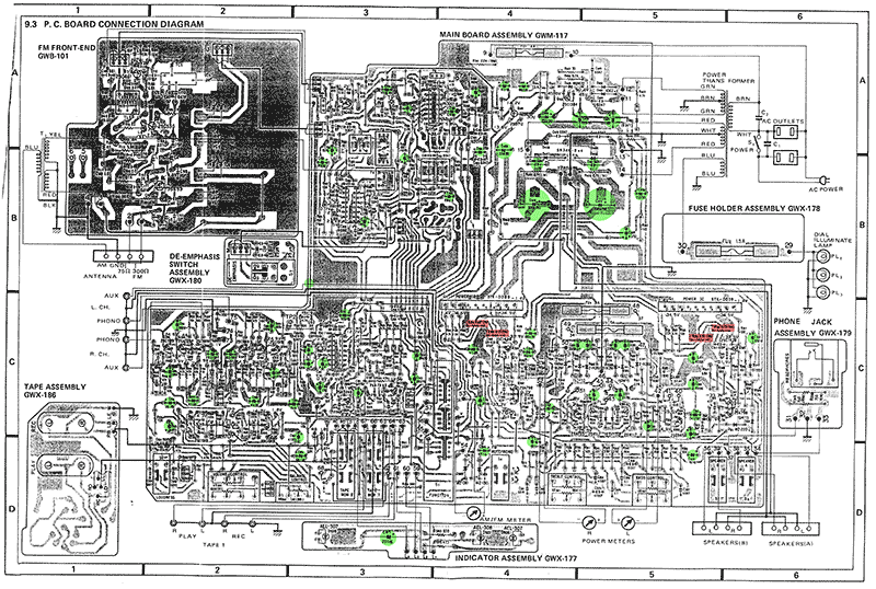
For a large copy of the image above, click here to download. I keep this up on my screen (zoomed in) while I work to easily find the components that need replacing – and their location on the PCB board.
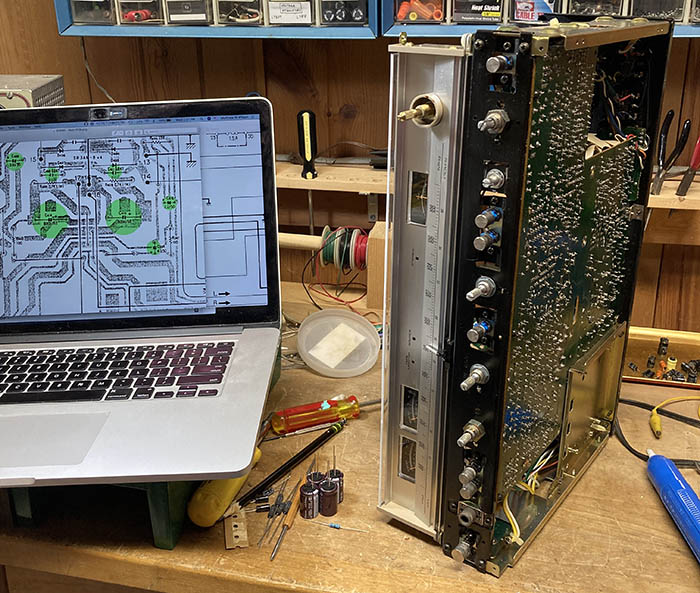
Another technique I use is to mark every component I replace with a red dot – this makes it easy to tell what’s been done and what hasn’t.
Glued-on Capacitors!?!
You will notice in the power supply section the larger capacitors have a brownish adhesive that bonds them to the PCB board. This is to prevent them from wiggling around and breaking the solder joints.
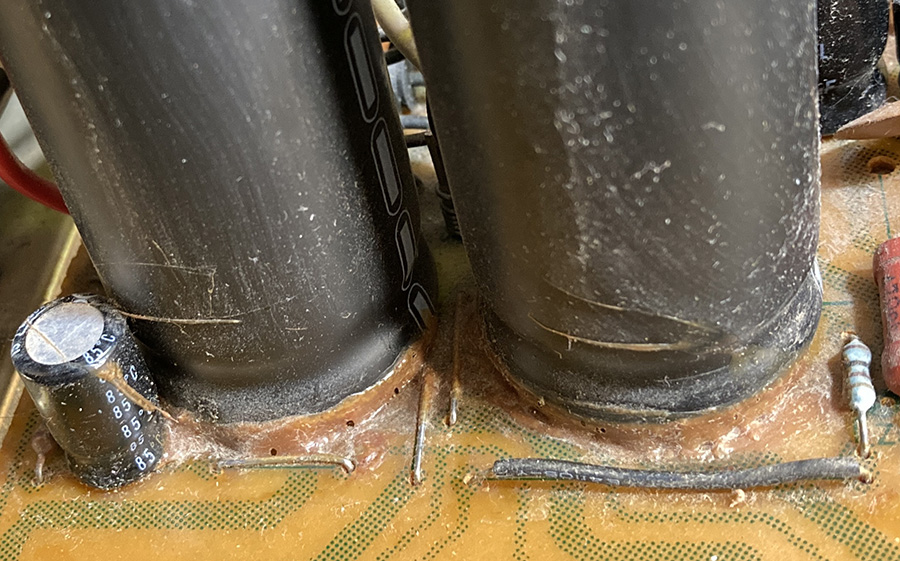
This dried brown glue must be carefully removed to free the capacitor from the board. I used a small X-Acto knife to carefully cut through the adhesive.
On the large capacitors, note there are THREE solder points to desolder – I didn’t realize this at first and cracked the PCB when trying to remove the capacitor! 😱
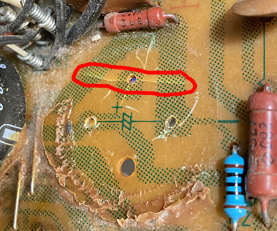
Luckily, the crack did not affect the copper traces on the other side of the board – which seemed just fine with full continuity.
Once old caps were successfully removed, new caps could go in – after being certain that the polarity of positive and negative leads were correct. I usually take photos to refer to – but the markings on this PCB were all correct.
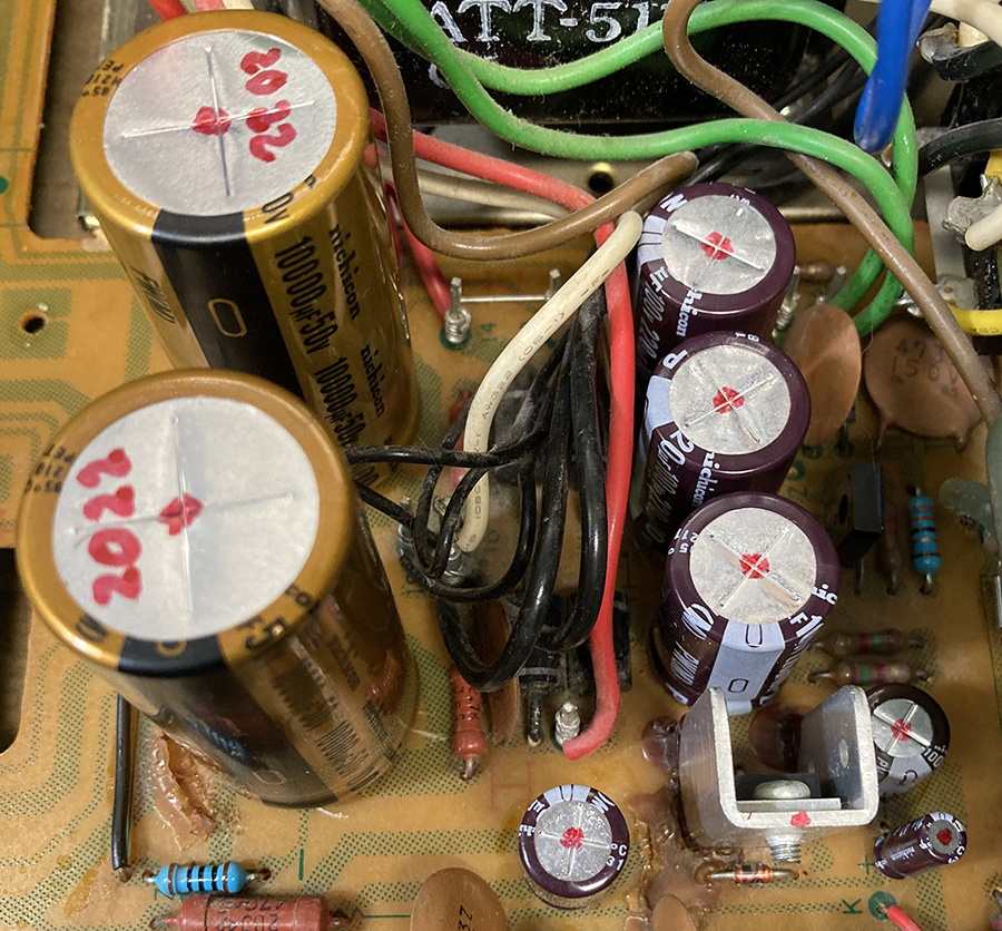
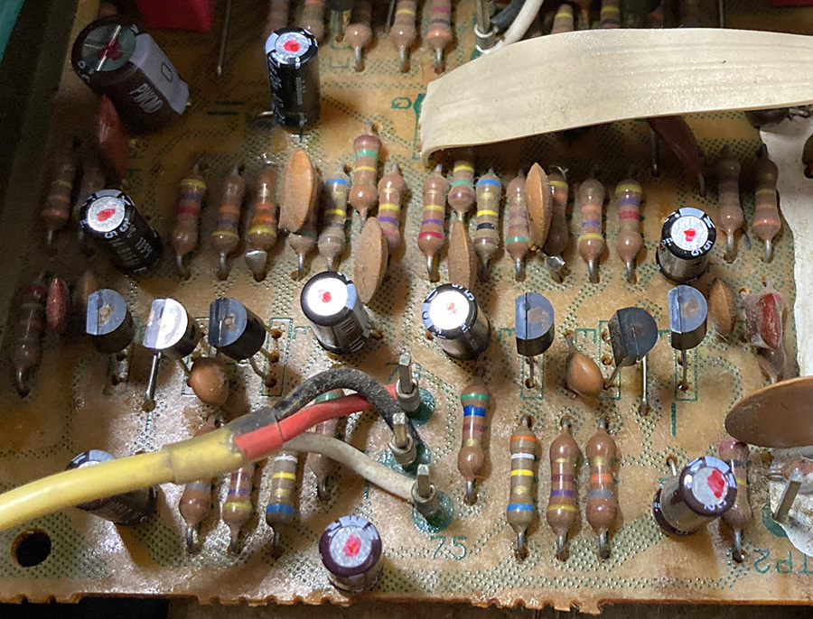
Here’s a shot of the final power supply section:
Transistor Upgrades
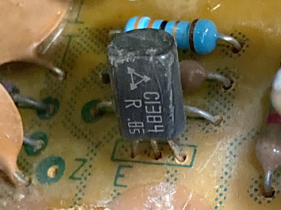
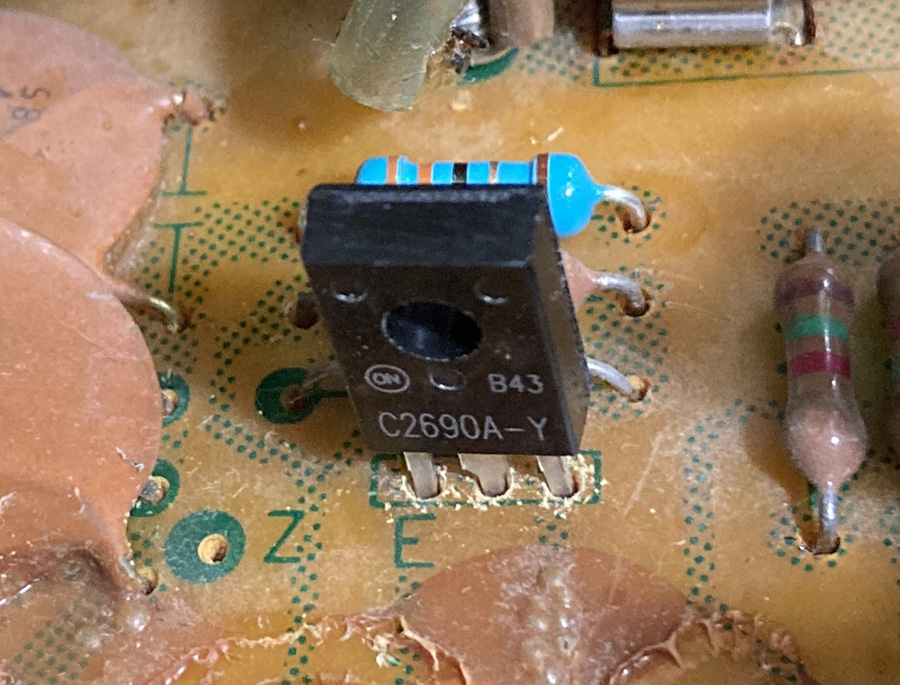
Two transistors in the power supply are recommended to be upgraded: The 2SC1384 (Q402) and the 2SD712 (Q302).
2SC1384 can be replaced with a modern equivalent: KSC2690AYS.
Q302 is a 2SD712 and must be carefully unscrewed from its heat sink. Remove old thermal compound with a q-tip and 91% isopropyl alcohol. Replace with a KSC2073TU – apply a thin layer of thermal compound and screw back to heat sink – being careful not to screw too tightly.
There are also six transistors in the phono preamp section that are recommended to replace: Four 2SC1919 transistors and two 2SA725 transistors. Note that the modern equivalents (KSC1845 and KSA992) have opposite pinouts and must be correctly aligned. Also note that as of this month (January of 2022), these two transistors are VERY difficult to source due to the pandemic wreaking havoc on the manufacturing and supply chain. My only advice is to buy from reputable sources. Luckily, I had a bunch on hand from previous restorations.
Testing the Pioneer SX-680 Rebuild
After a very late night on Christmas eve working in Santa’s workshop, I got everything completed and in a very exciting moment of truth at 2:00 a.m., I put everything back together and turned it on. Everything worked fine – and no magic smoke was released – we done good. ^_^
Here’s that initial moment, playing a Fela cassette through my less-than-ideal shop speakers:
The next day on Christmas, my brother-in-law was VERY pleased! 
We gave it a test run in the living room to see how it sounded through my Sansui SP-2500 speakers.
The SX-680 gets plenty loud – At 3-4, the volume was quite substantial and this would probably be my normal listening level. Very enjoyable and detailed. By 5 (“noon” on the volume control), the sound was nearly shaking the walls! In a larger space you might need a bit more volume but I never felt the need to increase volume past five – which will probably ensure a good long life for those hard-to-replace power packs.
Great stereo for a listening room, living room, music room, or bedroom. Excellent sound – very warm and lively. If you can find one of these at a good price – they are well-worth restoring!
Are you a business or do you rebuild these as a hobby. Need someone to work on one no electronic people in my area thank you
Hi David, Sorry for the late response! I just rebuild stuff for myself or friends. I have a full-time job so this is just a hobby. Good luck getting yours fixed! You might try a Facebook Group called Vintage Audio Enthusiasts and Technicians to help you find a repairperson in your area.
Good info, thanks for the write-up. I have an SX-950 I’ve had for probably 15 years. Set it on the bench several years ago and diagnosed, and it’s leaking DC out one channel a little bit. Idk if it’s discrete, or uses the STK pack. Getting anxious to get back into it since I picked up a Pioneer reel to reel recently.
Hi Steve – thanks for the comment. The SX-950 does not use STK packs. If it is “leaking DC” on one channel I am guessing you mean that the idle current is off? There is a procedure to adjust idle current for each channel on p. 38 of the service manual – which you can download for free at HiFiEngine. Good luck on it – I have an SX-980 as my main receiver and love it!