

In part 1 of this repair of an Airline GA 2940, I rebuilt the power supply and attempted to track down the source of a hum in the signal – which I traced to the output transistors. In this post, I’ll learn more about the output stage and replace the old germanium transistors with modern silicon.
The Output Stage: Class-B Transformer-Coupled Amplifier
My first task was to better understand the output stage circuitry of the amplifier. I had never experienced this sort of configuration before – which is often found in early solid state amplifiers and transistor radios.
Let’s take a look at the output stage of one channel:
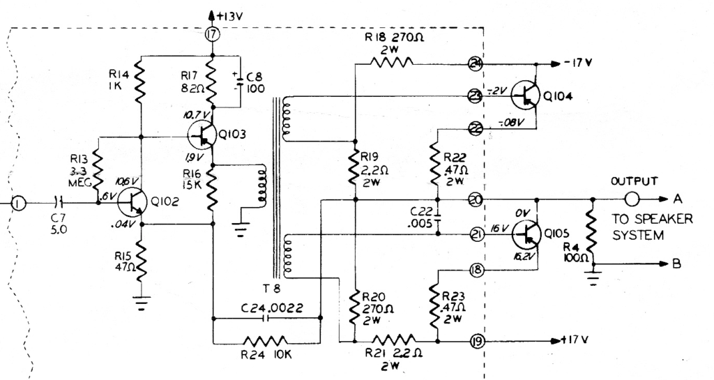
Note that this channel has two power transistors (Q104 and Q105) which are supplied with either negative or positive voltage (-17v and +17v) from the power supply.
These transistors are fed signal from separate secondary windings of an output transformer (T8).
In Solid State Servicing by William Sloot (Howard W. Sams, 1972), the author describes the operation of this circuit:
“Amplifiers of this type are usually referred to as class B amplifiers. In actual practice, however, transistor audio amplifiers are never operated class B because crossover distortion will result. This distortion arises as a consequence of the inherent emitter-base diode voltage drop. The transistor is not forward biased until applied, causing a constant, small, quiescent (no-signal) current to flow. This operation, strictly speaking is class AB.”
Since I had traced the noise issue to this stage, I suspected the output transistors – and Sloot notes that “Output transistor failure is the most likely malfunction in this type of amplifier due to the high power levels being handled.”
The Output Transistors
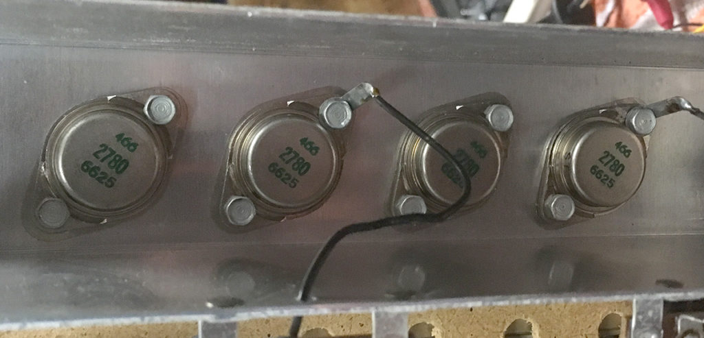
The power transistors in the Airline GA 2940 are listed in the parts list as DTG 110. The DTG 110 is a germanium power transistor in a TO-3 case manufactured by Delco in the mid 1960s. The transistors in the Airline have a different part number (466 2780 6625), most likely rebranded.
While NOS DTG 110 transistors can still be found, they are quite expensive, running at $35 – 60 apiece. Even a generic NTE 121 equivalent runs $25-40.
Testing the DTG 110 transistors in the Airline console revealed them to be leaky and noisy – but replacing four of them would be far too expensive for this rebuild. It was necessary to find a silicon PNP transistor in a TO-3 case.
Fortunately, R. G. Keen, a rebuilder of Vox solid state amplifiers that also use the DTG 110 wrote an excellent guide to replacing germanium power transistors that proved very helpful.
In it, he recommends the MJ15016 PNP silicon transistor as a suitable PNP replacement for the DTG 110. It can handle much higher voltages and current than this amplifier can produce – plus it has the advantage of being able to handle much higher temperature ranges than germanium, which is more sensitive to temperature changes.
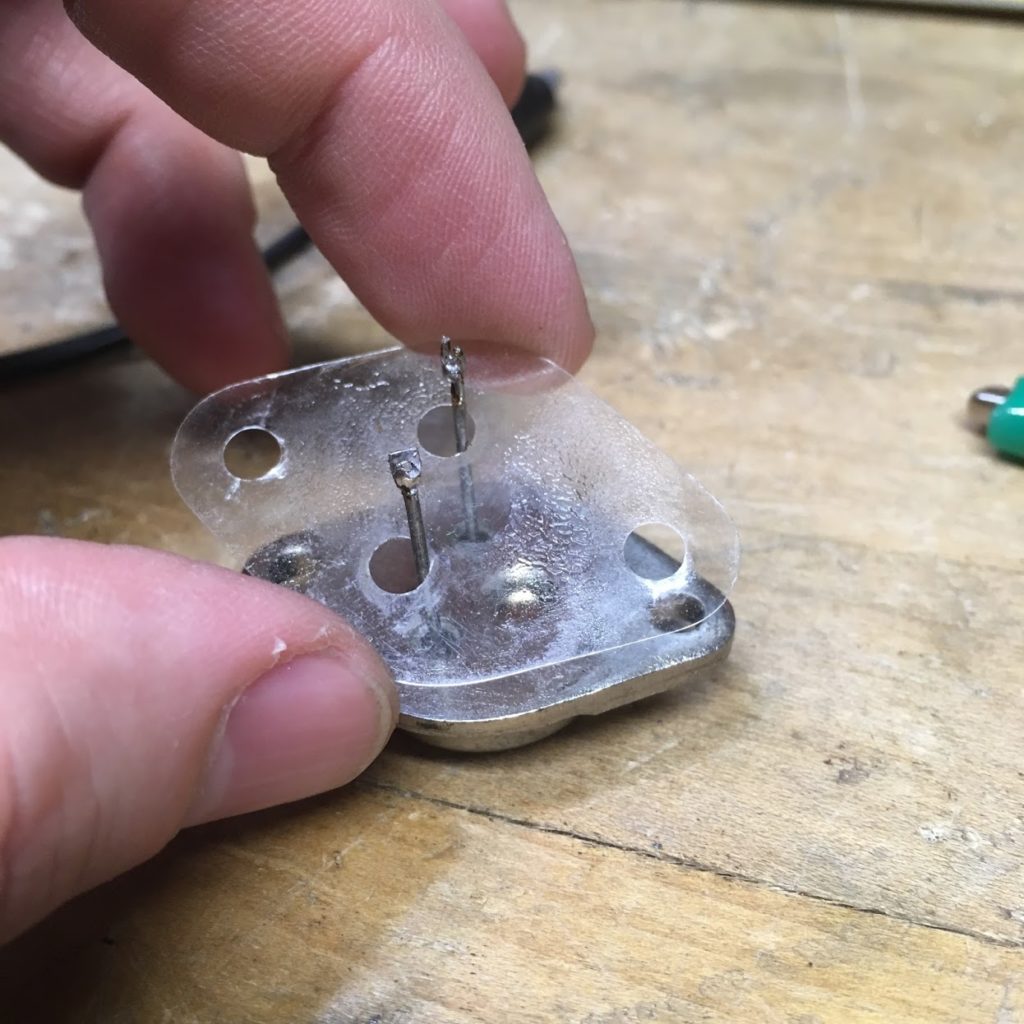
After removing the old germanium transistors, I carefully cleaned off the thin film that serves to isolate the body of the transistor from the chassis and applied put some new thermalcote on it before installing the new silicon transistors.
Re-Biasing the Transistors
In his instructions, Keen notes that when replacing germanium power transistors with silicon, the circuit must be re-biased.
Germanium transistors have a forward bias voltage of 0.3v while Silicon transistors have a forward bias voltage of 0.6v. This means replacing the output transistors will require a slight re-bias. Leaving the circuit as is would result in crossover distortion, as the silicon transistors would not “turn on” until audio signal level reached a certain level.
The 1964 GE Transistor Manual gives a general rule-of-thumb for adjusting the base-emitter bias of a transistor:
- Moving base toward the collector voltage supply turns the transistor ON
- Moving base away from the collector voltage supply turns the transistor OFF
![]()
So looking back at our output circuit, we can either decrease the value of our 270 ohm resistors (R18 and R20) or increase the value of our 2.2 ohm resistors (R19 and R21).

I chose to increase the value of the 2.2 ohm resistor since I could go up in very small steps (4.7 ohms, 6.8 ohms, 8.2 ohms, 10 ohms, 12 ohms, etc). R.G. Keen noted that increasing the resistance by 3x – 4x is a good starting point, so I began with 6.8 ohms. Here are the results for the different values on the scope after inserting a sine wave into the tape input:

As you can see, crossover distortion was continually reduced until at 10 ohms it is unnoticeable. That’s the value I settled on.
[Note for nerds: The irregular height of the crossover is due to the fact that at this time in the repair, the positive and negative voltage rails were quite unbalanced – the positive rail was around +14v and the negative rail was around -20v]
Continuing to increase this value would continue to increase the quiescent current flowing through the transistor – and eventually lead to thermal runaway (overheating). For science, I tried using 25 ohm resistors and turned the unit on for around a minute. The transistors heated up VERY quickly and were hot to the touch in that short time. Good thing the MJ15016 is a hardy transistor!
After changing out these resistors in both channels and installing the new output transistors, This output circuit sounded much better! Much more clean, clear, and quiet compared to the leaky and noisy germanium transistors. The hum also disappeared.
Enjoy the first record I played on the finished console:
FM has humming, not AM. Same fix? Where do you buy parts? What should reasonable price be to fix?
If FM has hum but not AM, this is a different issue than the one I covered. I buy parts from Mouser, Digi-Key, and other sources. A reasonable price to completely restore a console like this would be $250-400. A simple repair on an otherwise working console would be cheaper. FM circuits are complex, though – make sure you have a good tech.
can you please add information on these transformers ( separate secondary windings ), details , model , and if still been made
thank you
I’m sorry – I don’t have any information on the various transformers used in this console – it is no longer in my possession.
I need info on a qp5 to3 transistor in my Scott 4312 tuner hybrid nuvister front end Where can I get a schematic for it
Looks like there is a schematic for the 4312 available on hifiengine.
https://www.hifiengine.com/manual_library/hh-scott/4312.shtml
I don’t have specific info on QP5, but this discussion might be helpful:
https://www.antiqueradios.com/forums/viewtopic.php?f=13&t=234271&hilit=scott+312
The arm with needle in it does not work automatic, you need to move by hand. Any idea what may me wrong?
Probably need to disassemble the record changer and degrease it. Then reassemble, re-greasing as needed. This video will show you the basics of doing so on a VM changer:
Hello tubesandtransistors!
This blog and the processes you described to fix it sounds exactly like the problem I’m having with my Wards Airline Console, model number GHJ 2647A.
I completed restored the wood and speaker cloth myself!
I made a video describing the hum I’m having. If you wouldn’t mind checking this out and letting me know if there is hope in trying to make this hum go away. I’ve had the power cord professionally replaced as well as having all the of electrolytic capacitors replaced, as I’m not at all an electrician.
The video shown also shows the schematic.
-Please help! I love this stereo console and I want so bad for this hum to go away.
P.S.
I kept the turn table that came with the console and had that restored as well. The problem with it is that it cannot play 180 gram records without the needle sliding , but will play older records just fine. Would you happen to know if there is a fix for this as well?
https://www.youtube.com/watch?v=RDO6ctB75Wg